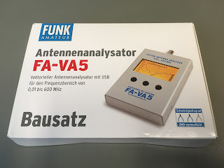
FA-VA5 is a high precision 600 MHz Antenna Analyzer for measurements of antennas, cables and other one port devices.
The VA5 is a
portable, full-featured Vector Measuring Device with a frequency range of 10
kHz to 600 MHz, with the added benefit of a USB port for connection to a
computer.
The
designer, Michael Knitter DG5MK, has taken feedback from users of the previous
VA4 instrument and incorporated many of the requested new features in the VA5,
whilst maintaining high performance and excellent value for money.
·
Frequency Range 10 kHz - 600 MHz
·
Small dimensions 15 x 8.5 x 2.2 cm - fully portable
·
User friendly - intuitive menus
·
Large display with good readability
·
Low power consumption (up to 40 hours from 2 AA batteries)
·
SOL Calibration function
·
USB-interface with support of the DG8SAQ VNWA Software
·
Real time clock with backup capacitor
·
Audible buzzer alert for minimum SWR alignment
The FA-VA5's graphic display shows the complex
impedance, standing wave ratio, complex reflection coefficient, capacitance and
inductance.
Vector’s measurement means that, unlike a scalar instrument, not only the SWR is measured and displayed, but also the value of the impedance, including the signed imaginary part. The so-called SOL (Short, Open and Load) compensation is used for the calibration of the device and provides precise measurements in different configurations.
Vector’s measurement means that, unlike a scalar instrument, not only the SWR is measured and displayed, but also the value of the impedance, including the signed imaginary part. The so-called SOL (Short, Open and Load) compensation is used for the calibration of the device and provides precise measurements in different configurations.
Have a look what you will get in the package and how
assembly the analyzer…
The kit is
double boxed with instruction manual
In two separated packages you will get PCB with
pre-installed SMD parts and bag of thru hole parts including the LCD display
which need to be soldered.
The instruction manual is detailed, precise and I am
recommending to following all step by step.
Anyway I will highlight few important things which
should help you during the assembling and it should avoid issues.
Motherboard
PCB with ON/OFF switch and USB module installed
Before the installation of the USB module you have
to ensure that insulating mica foil is correctly placed on the bottom of the
board > in between the USB board PCB and motherboard PCB.
Correct
place of the mica
Most important part of the assembling procedure is
the LCD panel installation on the motherboard PCB. I am recommending to using
three spacers instead of two pieces (recommended in the instruction manual) in
order to avoid bending the headers and possibly LCD itself when you will press
the fingers on the top during the soldering phase.
Three
spacers used to avoid bending the headers during soldering
The rest of thru hole parts assembling should not
make any troubles. Just be careful and do not overheating the switches and
other plastic components while soldering them on the motherboard PCB. Specially
the BNC socket used in the kit is cheapest component using the crappy plastic
insulation inside so you must be quite careful during the soldering it on the
PCB.
CAUTION:
Do not overheating this component otherwise you can melt the insulation part
inside and most important part of analyzer – the measuring port could failure
due to inserting the DUT (movement causing short circuit or so)
You should also double check the polarity
orientation of the both AA cells holders before soldering them to PCB.
All parts
assembled on the motherboard PCB
Correct
height of the LCD panel and well assembled input port BNC
The SMD
components are pre-assembled on arrival
Housing the
analyzer using pre-drilled box. All fits perfectly
After the assembling the analyzer it should work for
the first time. Do not use the charging AA cells as it will not work because of
their low voltage.
Initial
screen should be displayed after turning ON the analyzer.
Building document done by P. Ourednik,
9-Mar-2020. Document 03-20, rev.1.0
73 - Petr, OK1RP


No comments:
Post a Comment