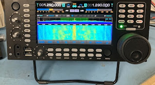
18 November 2024

All Digital Transceiver ADT-200A by HB9CBU part II. - First short performance tests

Subject: Receiver performance comparison

This experiment compares the basic receiver performance of the ADT-200A with known reference unit on the same antenna. Settings on both units: Band: 20m Mode: CW BW: 200Hz NB: OFF Notch: OFF AGC: fast AGC threshold (ADT): -80dBm

https://youtu.be/M7_gULhDwaU?si=dKPX4cNS3BLiPCdO Results: ADT receiver sounds much more selective as same as the BDR sounds better for close-in signals on the band. Signal S9 +40dB in the pileup just 1kHz away sounds strange on KX3 compared to ADT where it is also hearable but much weaker...


Subject: Receiver performance initial test This experiment shows receiver performance of the ADT-200A with different AGC and filters settings. Settings: Band: 20m Mode: CW BW: 50 - 500Hz NB1, NB2: OFF Notch: OFF AGC: fast AGC threshold (ADT): -80dBm Attack: 2ms Hold: 100ms Decay: 500ms

https://youtu.be/1SUs4nJdr6k?si=Tjujl6shEIGKenY3 Results: Amazing selectivity and high BDR for close-in signals, beautiful sound with smooth low-noise at -80dBm AGC threshold. Narrow filters are so effective that station need to be tuned quite precisely.

More info here:

ADAT page         - ADAT by HB9CBU


73 - Petr, OK1RP

01 November 2024

All Digital Transceiver ADT-200A by HB9CBU part I. - First introduction

The ADT-200A is world's first amateur radio transceiver with completely digital signal processing. The device is equipped with the latest DSP technology, moreover it is produced professionally with state-of-the-art technology.

The software algorithms for the signal processing have been carefully developed and have been optimized several times. Tests show that the ADT-200A can keep up with even the best commercial receivers regarding selectivity, sensitivity and intelligibility.

As a novelty, the transmit signal is processed by adaptive predistortion, a technique that is used for the first time in amateur radio. This technology stands out due to high efficiency and a remarkably clean transmit spectrum, combined with an exceptionally clear modulation.

The spectrum analyzer is available as a PC program. The display range extends from 10kHz up to 2MHz. This equally allows narrowband analysis of transmit spectra as well as monitoring of whole bands. A dynamic range of >120dB and an accuracy of ±1dB make this option a measuring instrument.


What is the Difference between an All-Digital and a conventional Receiver?


Most of today's conventional receivers are based on the tripple conversion concept. More often, DSP's are placed in the third IF stage. The most important performance criteria like intermodulation, reciprocal mixing, blocking and the selectivity of roofing filter can no longer be influenced by the DSP, because these parameters are already determined in the preceding analog stages. Due to the large number of components, it is difficult to achieve tight performance parameters during mass production.


In the digital receiver the full signal spectrum is fed directly to a high-resolution A/D converter. All signal processing is made digitally, which is ideal as it relates to distortions and noise. Since algorithms are determined by software, uniform performance parameters are obtained. Another benefit of this technology is the high degree of functional flexibility. New functions can be added by simple software download.


The Highlights of the ADT-200A

Receiver

  • Receiver with very clean, low-noise audio reproduction
  • 4 receivers with independent frequency selection, one is reserved for the Spectrum Analyzer
  • Automatic fine tuning for AM and CW via push button
  • Several noise blankers eliminate even extreme impulses
  • Linear S-meter with an unbelievable range of -148dBm up to +17dBm and a typical error of ±1dB

Transmitter

  • Adaptive Predistortion allows a PA efficiency of up to 70% and results in a very clean modulation
  • Low distortion voice enhancer replaces the legacy speech compressor
  • Clean output spectrum with an intermodulation ratio of >45dBc
  • Calibrated VSWR- and power meter working from 100mW

More info here:

ADAT page         ADAT by HB9CBU

18 July 2024

Hunting in Africa by Paul, EI5DI

Hunting in Africa:


You're ready - sitting quietly, not making a sound. You've been waiting for hours and your eyes are beginning to feel the strain. Just then, a wildebeest slowly ambles into view. It has no idea you're there. You've paid good money for this - every shot must count, so you're not going to miss. You aim carefully, check the wind gauge, hold your breath and, in-between heartbeats, fire. Bang, and 170ms later the wildebeest drops to the ground. The great white hunter strikes again!

You've just shot a wildebeest, and it's lying there, dead. The only difference is it's in the Serengeti, and you're in your apartment on Manhattan's Upper East Side.

This remote-controlled rifle is wonderful. From the comfort of your own home you know what it's like to be on safari and, to prove it, you've bagged a wildebeest.

You haven't had as much fun in ages. Like most of us, you don't have the time or money to actually go to Africa, so you have no other option - there's not so many wildebeest roaming Central Park these days. Apart from that, you're not as young or as mobile as you used to be, and the virtual-reality headset really makes up for your declining eyesight. After all, there's no point in having new technology and not using it - it can't be uninvented and it's not about to go away anytime soon. Travel is all very well for those with money to burn, but this is the real world and the only way you're ever going to add a wildebeest to your collection. In any case, you're an experienced hunter, with a licence to hunt in the Serengeti - so it's all above board.

No one can argue. You, alone, fired the shot. It's exactly the same as if you had been there (or if you had very long arms); the bullet travelled the same distance and the wildebeest is every bit as dead. In some ways it was even harder, because you had to allow for latency as well as wind speed. Oh no, they can't take that away from you (reminds me of a song) - except, of course, you were not there and you have not been hunting in Africa.

You should be ashamed of yourself. What you have done is both a travesty and a mockery. You have brought hunting into disrepute. If you want to hunt in Africa, go there because that's what hunters do. If you want to play amateur radio in Africa or anywhere else, go there because that's what self-respecting DXers and contesters do.


. . . . . . . . . . . . . . . . . . . .

This extract is from the ARRL Contest Update of 11th April 2012, regarding an entry in CQ WPX SSB.

http://www.arrl.org/contest-update-issues?issue=2012-04-11

"OH2UA was at the controls of CQ8X". . . . "the 4543
contacts were made over a remote link across the Internet
- 4500 kilometers from the actual station!"

Seems that Ward N0AX, the Contest Update editor, is impressed by distance on the internet.

73,
Paul EI5DI

--
Remote Operating

Return to ei5di.com

16 July 2024

QMX - The multiband and multimode transceiver by QRP Labs - part I.

QRP Labs (Hans, G0UPL) says...

QMX: a feature-packed, high performance, 5-BAND 5W, CW and Digi-modes transceiver kit, including embedded SDR, 24-bit 48 ksps USB sound card, CAT control, synthesized VFO with TCXO reference.


More details about QMX:

The "QMX" (QRP Labs Multimode Xcvr): a feature-packed, high performance, five-band (80, 60, 40, 30 and 20m) 5W CW and Digi-modes transceiver kit, including embedded SDR receiver, 24-bit 48 ksps USB sound card, CAT control, synthesized VFO with TCXO reference. QMX may be used in CW modes standalone, or with a single USB cable to a PC for digi mode operation. QMX also incorporates standalone CW, FSKCW and WSPR beacon functionality (no PC connection required).

QMX transmits a SINGLE SIGNAL on FSK signal modes, it is not an SSB modulator with associated unwanted sideband and residual carrier, or intermodulation due to amplifier non-linearity. QMX outputs a pure single signal. QMX is, in the first firmware releases, suitable only for CW and single tone FSK modes, which covers the majority of digital modes in use today. This includes everything in WSJT-X, JS8Call, some fldigi modes e.g. RTTY, Olivia and more. QMX is not suitable for phase shift keyed modes such as PSK31 or modes involving multiple concurrent tones such as WinLink.


CW features

Excellent CW performance is and always will be a very high priority on all QRP Labs transceivers that include CW mode operation. QMX is of course no exception (there are no exceptions!).

In the graph below left you can see the measured CW filter performance of QMX (red line) vs the QCX-mini (blue line). The QMX filter is 300Hz wide (compared to the QCX-mini filter which is approximately 200Hz) but the QMX filter has much sharper edges. Both are centered on 700Hz. Note that in future QMX firmware releases, both the center frequency and the filter width will be configurable and adjustable.


Another very important feature is clean break-in operation (QSK) without audible clicks. I did a lot of work in this area to ensure that QMX has NO audible clicks at all on the transmit/receive changeover. The 700Hz sidetone frequency is a clean sinewave produced by a software emulated DDS (Direct Digital Synthesizer) running at 48ksps (kilo samples per second). The amplitude envelope of the sidetone has leading and trailing edges shaped as a raised cosine with 5ms rise/fall time. Sidetone therefore sounds extremely clean.


All transmit/receive switching in QMX is solid state (no relays) so is fast and clean. A common problem with SDR receivers is that the audio processing can have considerable latency; this is a killer for good break-in operation (QSK) because if the latency is slower than the CW dit (symbol length) then there is no time for the receiver to recover and produce any audio in the gaps between symbols and QSK is therefore impossible. SDR software running on a PC can be particularly problematic due to all the additional layers of latency involved in the operating system, as well as the DSP (digital signal processing) in the SDR itself. In QMX the SDR is implemented in the on-board powerful 168MHz 32-bit ARM Cortex M4 processor with Floating point and DSP instructions. It is therefore possible to closely control the latency performance.


In the audacity audio recordings below, the small amplitude trace is the sidetone during some CW keying. The huge amplitude tone is the reception of a massive S9++ signal injected into the QMX BNC port. It is possible to zoom in and measure the duration of the gap between key-up and the receive audio. The latency is approximately 15ms. This compares rather favorably with other well-respected transceivers:

Elecraft KX2: 40ms (source: ARRL QST review, May 2017)
Elecraft K3S: 14ms (source: ARRL QST review, November 2016)
QRP Labs QCX: 22ms (source: ARRL QST review, August 2019)
QRP Labs QMX: 15ms (my measurement)

Another method to measure the latency also yielded an almost identical result (15ms): using a dual channel digital 'scope with one channel connected to the RF input of the QMX and the other, the audio output, then enabling a gigantic RF signal. The digital 'scope allows accurate cursor measurements on a screen capture, the delay from RF into AF out measured 15ms. The audio in ADC and audio out DAC both operate on 32-sample blocks every 667 microseconds. Most of the 15ms delay is inherent in the Digital Signal Processing.


CPU

QDX is an embedded SDR. To provide the highest possible performance and scope for future features, a powerful STM32 microcontroller was chosen, the STM32F446. This is a 32-bit ARM Cortex M4 with floating point unit, DSP instructions, 512K Flash and 128K RAM, plenty of I/O and running at 168 MHz. It is by far the most poweful processor used on any QRP Labs product to date. At the QMX launch, well under 25% of the system resources are used.

More info here:
QMX manual - operation_1_00_020.pdf (qrp-labs.com)


73 - Petr, OK1RP

07 July 2023

Collins mechanical filters installation guide for Yaesu FT-8xx radios - updated 15-May-24

Collins mechanical filters installation guide for Yaesu FT-8xx radios

Even although this line of radios is obsolete (except FT-818ND) there is still many of people who are looking for installation guide of the optional filters... 


1. Type of filter

526-8733-010: 455.00kHz center frequency / 0.3kHz BW @ -3dB / 1.00kHz BW @ -60dB / -10dB insertion loss / 7-poles (simply 300Hz / 7-poles filter)


526-8733-010 (alias Inrad #712): 455.00kHz center frequency / 0.34kHz BW @ -6dB / 0.85kHz BW @ -60dB / -9dB insertion loss / 7-poles (simply 300Hz / 7-poles filter)


526-8733-020 (alias XF-115CN or YF-122CN): 455.00kHz center frequency / 0.3kHz BW @ -6dB / 1.00kHz BW @ -60dB / -10dB insertion loss / 7-poles (simply 300Hz / 7-poles filter)


526-8686-010: 455.00kHz center frequency / 0.45kHz BW @ -3dB / 2.00kHz BW @ -60dB / -5dB insertion loss / 7-poles (simply 500Hz / 7-poles filter)


526-8686-030 (alias XF-115C): 455.00kHz center frequency / 0.45kHz BW @ -6dB / 2.00kHz BW @ -60dB / -5dB insertion loss / 7-poles (simply 500Hz / 7-poles filter)


526-8686-030 (alias YF-122C): 455.00kHz center frequency / 0.5kHz BW @ -6dB / 2.00kHz BW @ -60dB / -5dB insertion loss / 7-poles (simply 500Hz / 7-poles filter)


526-8693-010 (alias AOR MF500 or YF-122C): 455.00kHz center frequency / 0.49kHz BW @ -3dB / 2.00kHz BW @ -60dB / -5dB insertion loss / 7-poles (simply 500Hz / 7-poles filter)


Collins (alias Inrad #705): 455.00kHz center frequency / 0.595kHz BW @ -6dB / 1.56kHz BW @ -60dB / -7dB insertion loss / 7-poles (marked as 500Hz / 7-poles filter)


526-8686-030 (alias YF-115C): 455.00kHz center frequency / 0.45kHz BW @ -6dB / 2.00kHz BW @ -60dB / -5dB insertion loss / 7-poles (simply 500Hz / 7-poles filter)


526-8693-010 (alias YF-115C or Inrad #705-C): 455.00kHz center frequency / 0.5kHz BW @ -3dB / 2.00kHz BW @ -60dB / -5dB insertion loss / 7-poles (simply 500Hz / 7-poles filter)


2. ESD protection

Install and use some ESD protection tools on bench like ESD mat grounded properly through 1.5MOhms resistor and wristband connected to the ESD mat at the corner.


3. Installation the filter (hardware)

For correct installation you can follow the manual for FT-817ND see page 74 (or respective FT-8xx version of radios).

Front panel view > slide into the socket while 3-pins are on the left and four pins are on the right side > filter case upwards. Push carefully on both sides at the same time to click into the headers.

Also you can check details here:
SP6AB radio blog: Home made CW YF-122C filter board for Yaesu FT-817/857/897


4. Filter board setup

Which filter is installed on the filter's PCB is defined by installed resistors combination.

If it is factory soldered, then do not care about it. 

If you installed yourself then check the proper resistors setup also on the link here:
SP6AB radio blog: Home made CW YF-122C filter board for Yaesu FT-817/857/897


5. Installation the filter (software) – Menu 38

After assembling the radio back and turning it on go to Menu 38 (long press F-button and turn the SEL knob on the left to position 38) and change the OP FILTER menu from OFF to CW in the middle row (by main dial knob). Then exit by long press F-button.


6. Activation the filter – NAR function

If all is ok and no ghostbusters in your radio, then now when you will short-press the F-button and using SEL knob you will find the IPO / ATT / NAR menu in third lowest row on the display > after pressing C-button (right under display) assigned to NAR function you should be able to select narrow filter for CW which is installed in radio. Also, it would be hearable by narrower and lower noise in speaker.

Note: For some reason some users are reporting that when trying to select CW position in Menu 38 there is only OFF and SSB... but after careful turning back and forth it should appear CW...


Hope it helps. 

73 - Petr, OK1RP
"Apple, Ten-Tec & Elecraft freak"
B:
http://ok1rp.blogspot.com
MeWe:
https://bit.ly/2HGPoDx
MeWe:
https://bit.ly/2FmwvDt


Installation document by P. Ourednik, 15-May-2024. Document 05-24, rev.4.0

25 April 2023

SBITX V2 - Hybrid SDR transceiver Part II. - Unboxing and installation

Sales of the SBITX V2 has been opened by HF Signals from 11-Apr-23 Monday morning. First units have been dispatched at around 19-Apr-23. I was really amazed how fast it went thru the continents as this unit was shipped on 19-Apr-23 and it arrived at my hands on 21-Apr-23 morning!

Well packed, labeled sn:0005 with signature from the person who was responsible for testing and packing all together. It looks cool and trusty.


There were not any issues with custom clearance using the DHL services just the VAT and DHL custom services fee had to be paid of course. 

The foams protecting the radio inside as same as the rest of accessories parts. Package includes radio, manual, packing list, mic, stereo jack3.5mm and 20cm of the power cable with XT60 power connector. This is now a common high amperage connector popular among the drone and r/c flyers. You will get a mating connector for this in your kit that can be soldered to any other kind of connector you may have on your power supply.


As the fully completed and tested radio has been ordered then the installation is easier and faster than in case of ordering unit without RASPi or even just assembled and tested transceiver PCB board.


After removing the radio from the box and plastic bag it is ready to plug in the power, antenna and run it. 


Attention: As it is not allowed to shipping electronics with batteries installed (in fact it is possible but special declaration and shipping conditions setup are needed and HF Signals did not manage that with DHL yet) please be note that your radio has not installed the RTC battery on the board. It is button cell CR 2032 type, and you will have to install it into the radio on arrival. (I will post some short article and pictorial how to do it soon)


After switching ON your radio and booting up the RASPi the desktop will appear in few seconds. Touch the sBitx icon to launch the radio itself.


The sBitx application will launch the browser. You will need to type in the passkey. The initial passkey is “123”. You can use the on-screen keyboard to type it in or use an attached physical keyboard then press Start.

Following the manual as a first-time user, you have to add some basic information to your radio. In fact, you can skip that step and add these information's any time later but as it is just callsign, your location grid you can do it now ...don't worry, it will happen :)

Btw: you can set up also the CW input (paddle, pump key or keyboard at this menu if you want)


Your radio is alive and together with the well-known screen you will hear the noise from the band.

Congrats! You are on the air with your new beast.


First test on the air with large beam here.

Open-source code and documents here. 

Manual can be download here.

Orders can be placed here.


73 - Petr, OK1RP

.../-.-

18 April 2023

Developer's Edition (DE) SBITX V1 - Bake oven?

The new SBITX V2 is the successor to the previous prototype version SBITX V1, which was only available in limited quantities as a development prototype marked "DE" (Developer's Edition). 

It featured a larger, compact case, a flat-mounted transceiver board, and a heatsink on the outside back.
 
And why do some like to call the SBITX V1_DE as a microwave oven or ham radio version of the bake oven? Judge for yourself... :)


Many owners quite liked the cabinet, and the nickname could have been adopted if the new SBITX V2 version had not brought design changes in addition of the changes on transceiver board. The depth of the cabinet is now one-third, transceiver board is located on the back and the new look of the housing is more reminiscent of a door opener...


73 - Petr, OK1RP
.../-.-